News Flash: Primanex MO Switch Passes ESA Test
May 21, 2019, Qingdao
It was learned recently that Primanex magneto-optical switch has successfully passed the complete test of the European Space Agency (referred to as ESA). Among the four vendors participating in the global competition, Primanex is the only Chinese company, and one of the three U.S. companies failed. This project is under the ESA Invitation-To-Tender (ITT) “Optical Switches with No Moving Parts for Space Applicaations”.
Optical switch is a basic building block for many optical systems and has been proposed for varieties of space applications due to its simple redundancy, fast isolation, low-speed modulation and the most basic beam path switching etc. ESA specifically listed eight types of space applications involving the use of optical switches:
1. CO2 monitoring lidar
2. Atom sensor-A/B (Wavelength 750/1580nm)
3. Optical sensing
4. Digital communication
5. Local oscillator-distribution
6. Optical communication
7. Optopyrotechnics
8. Laser interferometry
Different types of optical switches have been successfully applied to ground-based applications, such as fiber-optics communication and optical sensing; however, ESA has not conducted a comprehensive analysis of the prospective challenges and benefits by applying optical switches into space. Traditional mechanical optical switches, including bulk optical technology and MEMS technology, rely on moving parts to achieve light beam switching, hence are limited in the space field considering their disadvantages in reliability and switching speed. Therefore, the ITT is focused on the all-solid-state optical switches, which is jointly carried out by TUV Nord subsidiary Alter Technology, The Polytechnic University of Madrid and ESA. The candidate technologies include bulk electro-optic (B-EO), waveguide electro-optic (WG-EO), magneto-optic (MO), acousto-optic (AO), liquid crystal (LC) and thermo-optic (TO):
• TO technology is abandoned because there is no commercial product.
• LC technology is abandoned because there is no on-shelf product, and can only be tested through customized components. No vendor is willing to participate.
• AO technology is abandoned because its loss is more than 3dB, and the driving circuit is too much complicated. All applications require as minimum as possible insertion loss, in any case <3 dB and in some cases <1 dB.
• In the end, only three technologies and four vendors were selected for ITT, MO (Primanex, Agiltron), B-EO (Agiltron, BATi) and WG-EO (Epiphotonics).
The test plan is summarized below:
• Optical /electrical performances test: insertion loss (IL), crosstalk (CT), switching speed, polarization dependent loss (PDL), polarization extinction ratio (PER)
• Mechanical test: vibration, shock
• Thermal vacuum test
• Radiation test
• Destructive physical analysis
1. Vibration test
All DUTs (device-under-test) vibrate continuously in three orthogonal axes for three minutes, meanwhile they are switched in a periodicity of approximately 10 seconds.
The vibration parameters are as follows:
|
Frequency(Hertz) |
Satellite level |
|
20 |
0.52 g^2/Hz |
|
20~50 |
+6 dB/Octave |
|
80~800 |
0.32 g^2/Hz |
|
800~2000 |
-6 dB/Octave |
|
2000 |
0.052 g^2/Hz |
|
Total |
20 grms |
Vibration test site and the X-axis random vibration are shown below:
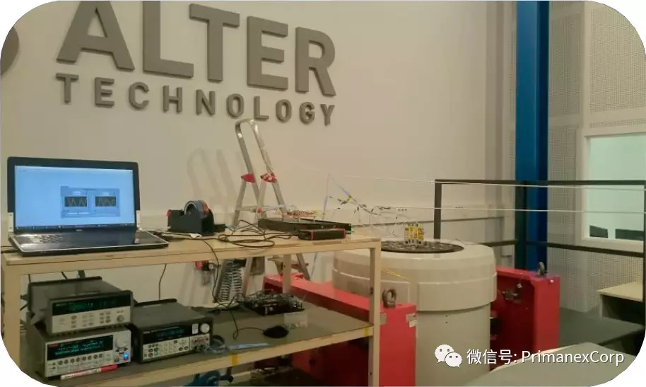
Figure 1: Vibration test site
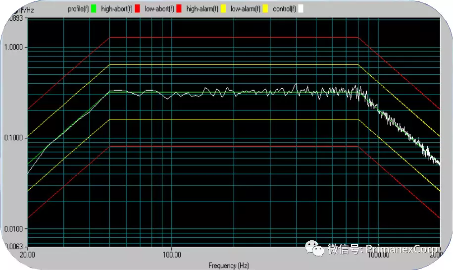
Figure 2: X-axis random vibration
The two states of "ON" and "OFF" are simultaneously in-situ tested for all optical outputs of all DUTs, thus IL and CT can be calculated. All DUTs passed the test successfully, and the results are shown below.
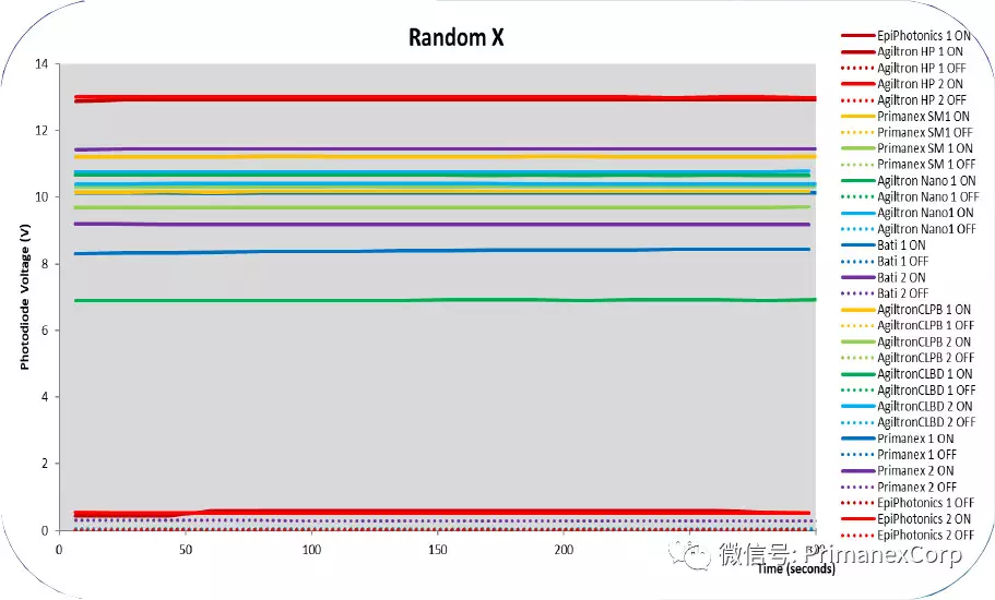
Figure 3: In-situ monitoring of optical power in X-axis random vibration
2. SRS impact test
All DUTs are tested by 500g half Sine Pulse 1 millisecond duration pulsed impacts in three orthogonal axes. No optical/electrical performances variation were observed in all DUTs after impacts. Only one of the EpiPhotonics products was damaged during the impact test, its input arm was unglued.
3. Thermal vacuum test
All DUTs are put inside the vacuum chamber for thermal cycling test with the conditions detailed below:
|
Vacuum temperature cycle parameter setting |
||
|
Lowest temperature |
-10 Celsius |
-5 Celsius |
|
Highest temperature |
75 Celsius |
70 Celsius |
|
Highest / lowest temperature residence time |
2 hours |
2 hours |
|
Furnace pressure |
Less than 10 ^-5 mbar |
Less than 10 ^-5 mbar |
|
Temperature change rate |
Less than 5 degrees per minute |
Less than 5 degrees per minute |
|
Cycle number |
1 |
7 |
Thermal vacuum test site and the monitoring results of optical power are shown below.
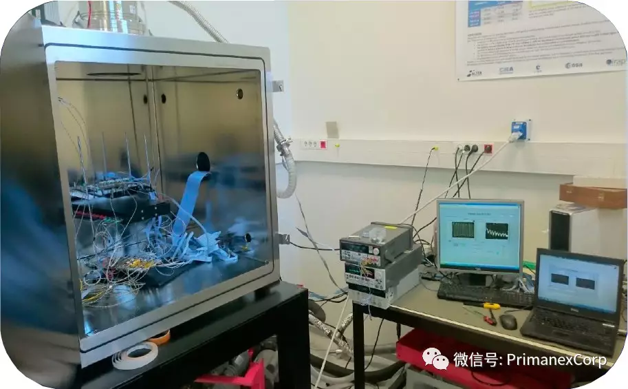
Figure 4: Thermal vacuum test site
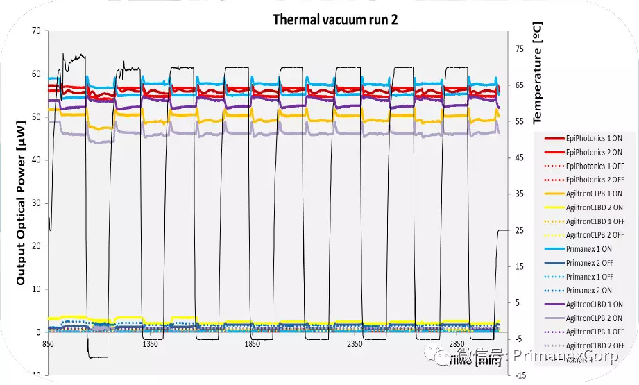
Figure 5: In-situ monitoring of optical power during thermal vacuum test
4. Radiation test
The Gamma radiation test was performed at the facilities of the National Center of Accelerators (CAN) in Seville, Spain. The dose rate is ~210 rad/(Si)h with an accumulated dose of ~100 krad/(Si) and a duration of ~480 hours.
The optical outputs of the DUTs are in-situ monitored during the test. The test site and monitoring results are shown below.
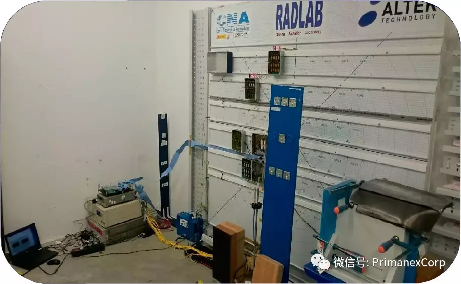
Figure 6: Gamma irradiation test site
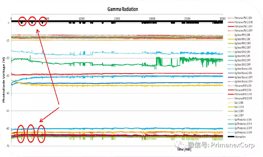
Figure 7: In-situ monitoring of optical power during radiation test
The interruptions of the radiation, inherent to the regular operation of the facility, are highlighted with black marks. These interruptions lasted less than 2 hours. Note that the output optical power is sensitive to the radiation interruption, mainly in the OFF states.
5. Destructive physical analysis
In the end a destructive physical analysis is made for some DUTs. Only one DUT from EpiPhotonics showed damage with its input fiber broken during the shock test.
The averaged standard deviation of all the measurements of each reference part type has been taken as a value of the uncertainty and the deviation of the values of each parameter after each test has been compared with this uncertainty. The Student’s t-distribution was used for this statistic. Judicious criteria were defined to decide whether a part type passed the test. According to these criteria all the tested samples, except the mentioned EpiPhotonics switch, passed all the tests.
Conclusion
1. For applications requiring higher switching speed, B-EO technology performs slightly better than MO technology. However, its crosstalk is worse.
2. MO technology shows excellent overall performances except for switching speed. And, this technology is commercially available.
3. WG-EO technology is very fast. It is believed that the mechanical failure can be solved. However, it is very complicated to operate, its loss is too high and crosstalk is too low. Its fast response can be obtained in B-EO technology, so it is not recommended for space applications.
4. Switches are more sensitive to temperature than to radiation and vibration.
5. No difference has been found between the behavior of polarization maintaining fibers and single mode fibers.
6. No difference has been found between the high power and the low power MO switches.
Based on these conclusions, Alter Technology, Polytechnic University of Madrid and ESA recommend:
1. B-EO technology and MO technology can be used for the space applications. B-EO technology should be used for applications requiring high switching speed while MO technology should be used for those applications requiring a minimum crosstalk.
2. To keep the device temperature constant if constant output power is required.